
An attempt at interactive e-textile design which avoids using a microcontroller or any programmable logic element. Laser cutter, vinyl cutter, and sewing machine were used for ease, but entire project can be done by hand.
Concept:
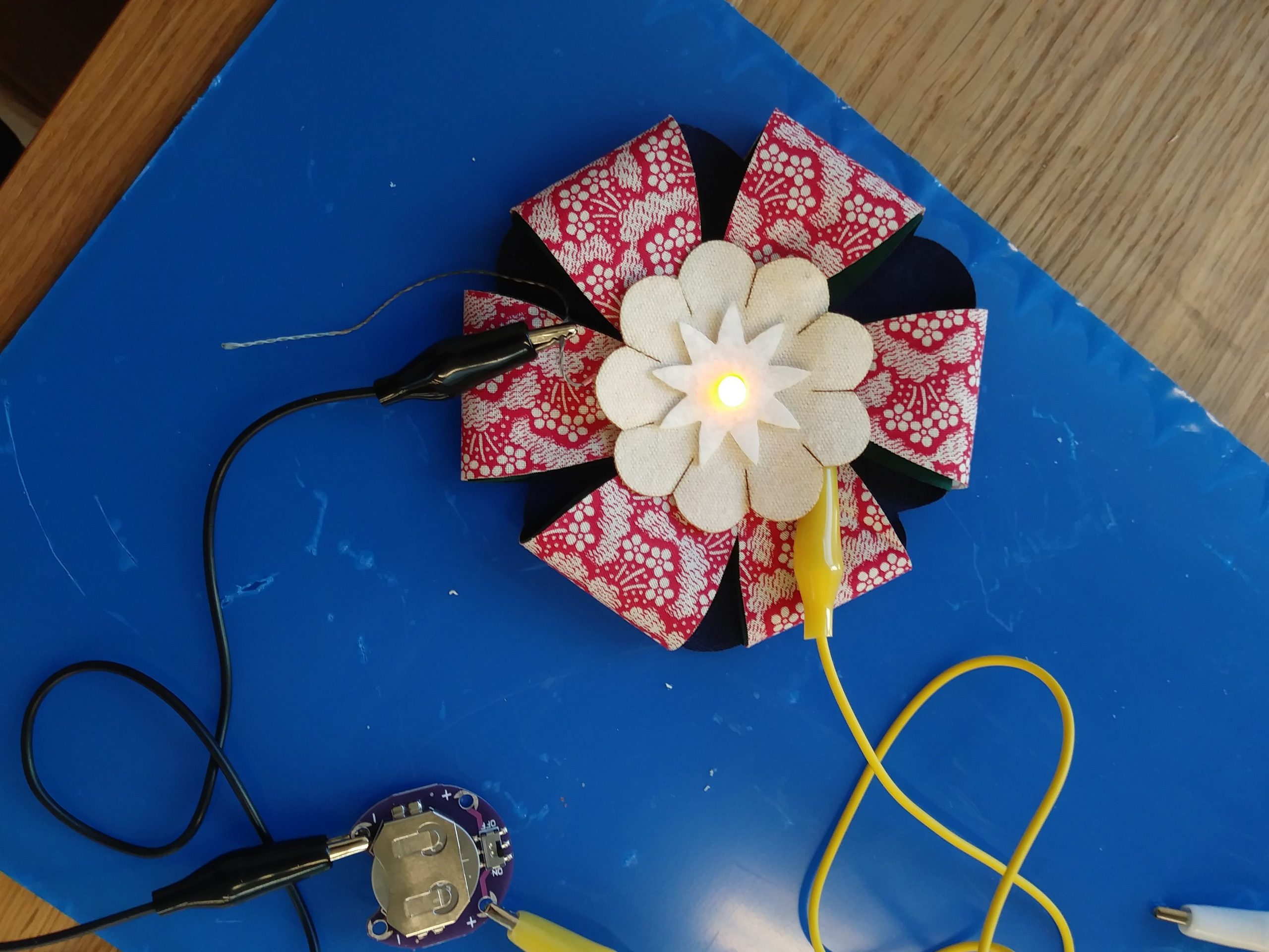
An LED Flower Brooch that changes colors, using petals as switches to change resistances for RGB channels, to generate up to 9 unique color combinations:
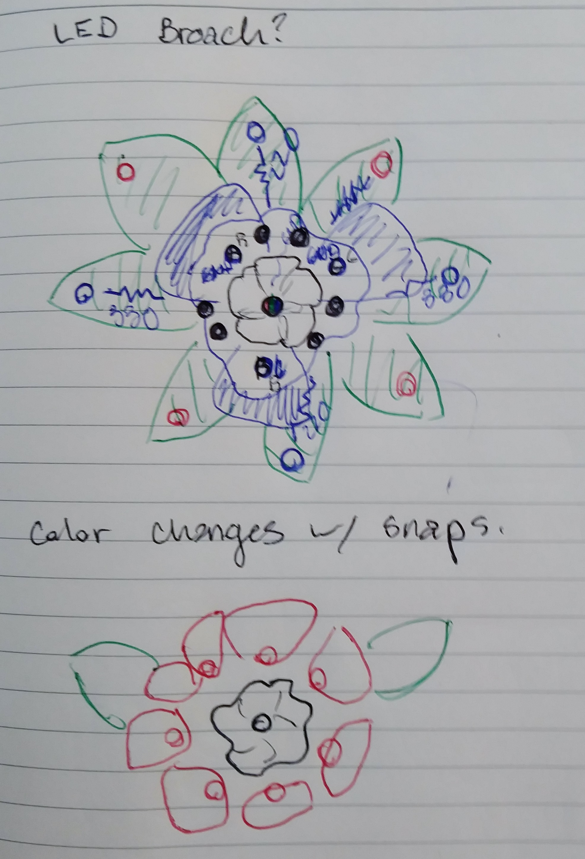
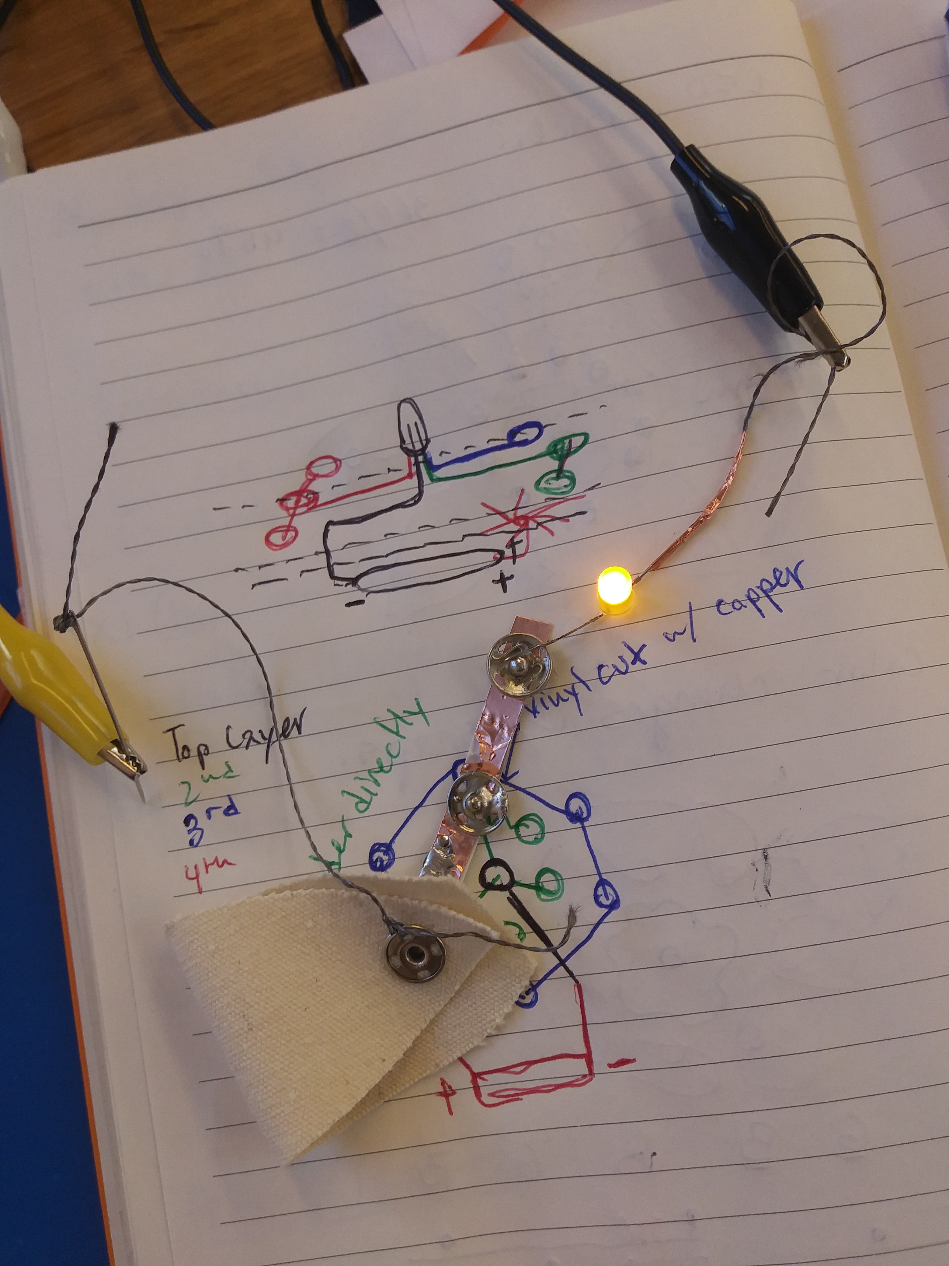
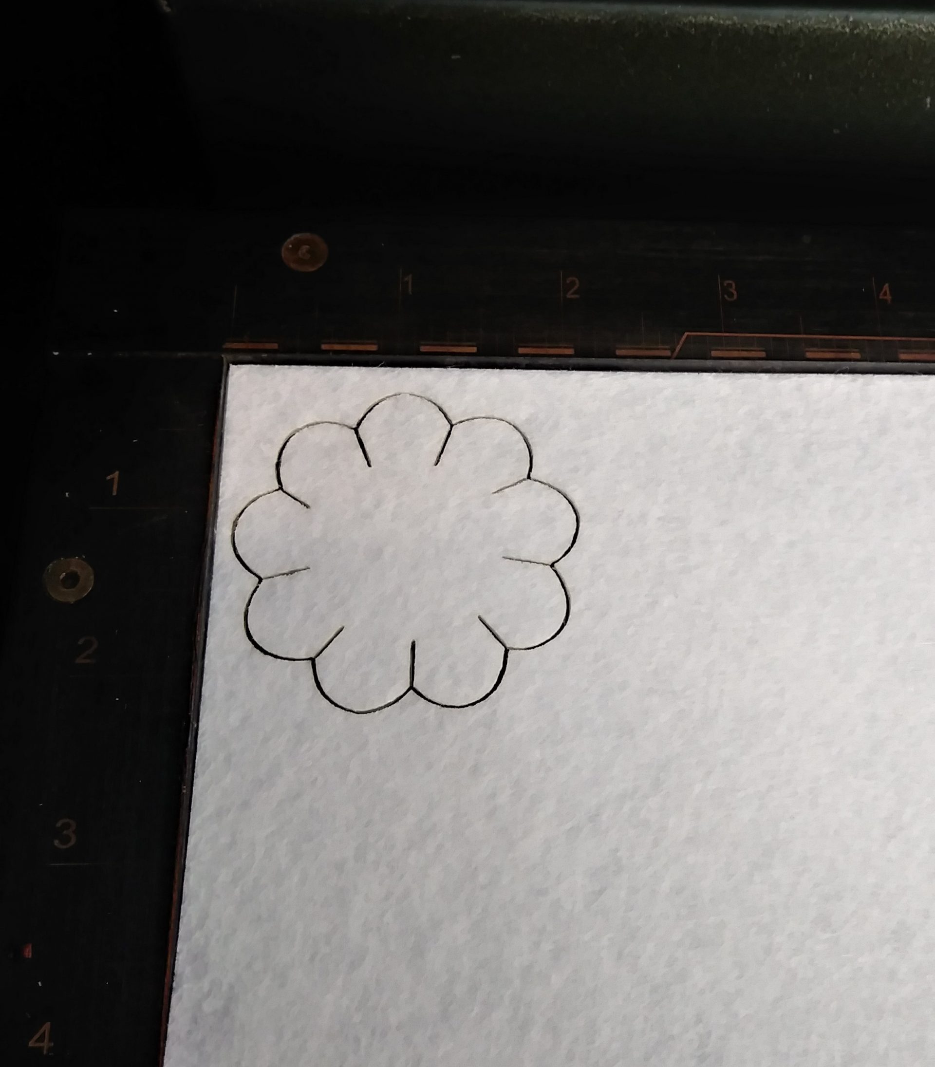
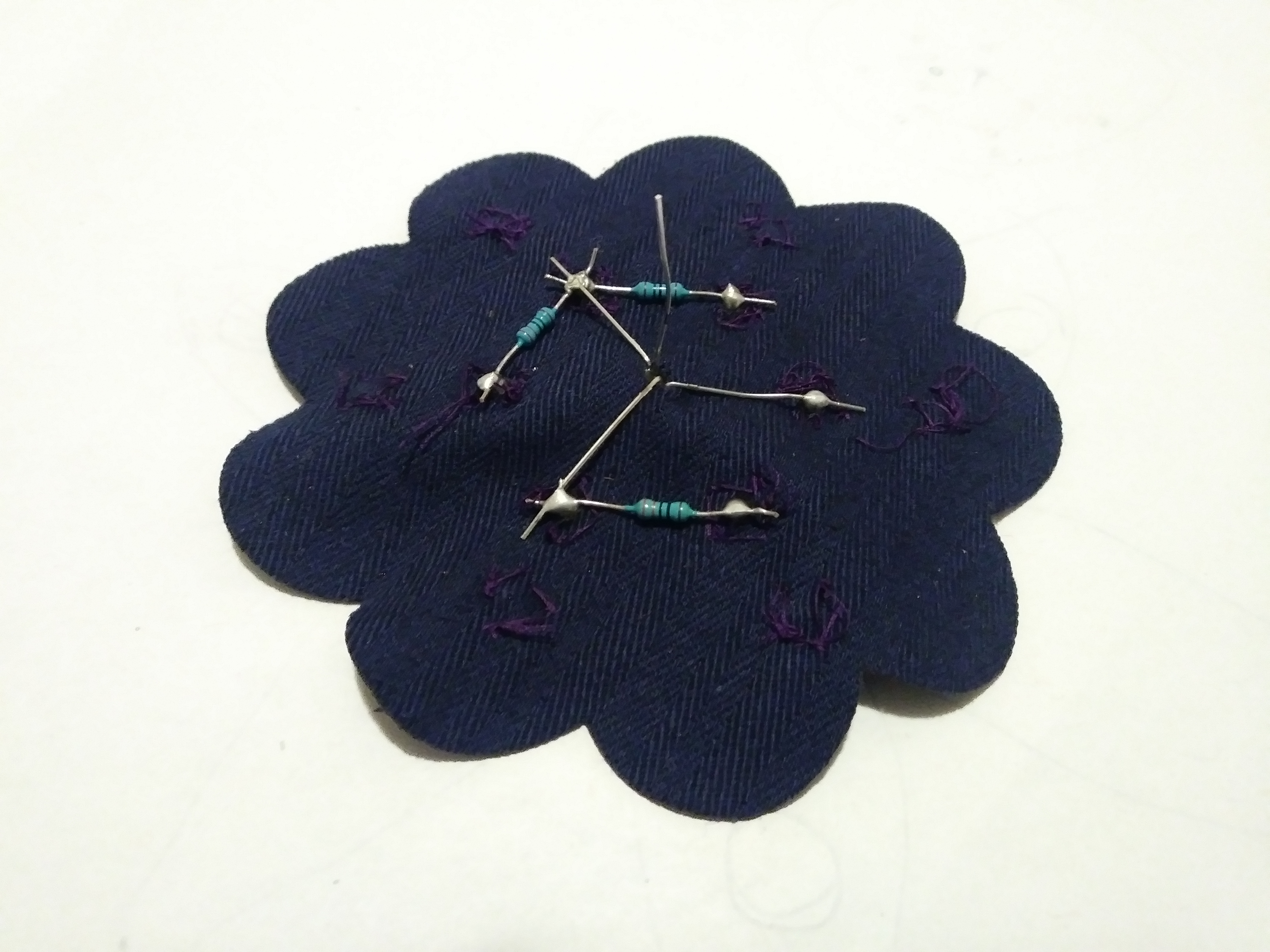
Initial concept + testing materials for solderability/conductivity
Color Combinations
| Desired Color | R | G | B |
|---|---|---|---|
| Red | X | ||
| Green | X | ||
| Blue | X | ||
| Cyan | 330 ohms | X | |
| Magenta | 100 ohms | X | |
| Yellow | 50 ohms | X | |
| White | X | X | X |
| Purple | 200 ohms | X | |
| Orange | 20 ohms | X |
Color combinations based off of RGB color theory. Because of the non-uniform brightness of the RGB elements, trial and error is required to obtain appropriate resistance values to balance each color combination. A combination of 6 channels with 4 different resistance values allowed for 9 unique colors to be achieved.
Design
Materials
- RGB LED (3 positive leads, 1 shared ground)
- Coin Cell Battery + Holder
- Conductive metal fabric snaps, silver (x6)
- Non-Conductive metal fabric snaps, black (x6)
- Adhesive-backed copper foil sheet.
- Resistors (100, 220, 330 Ohm)
- Scrap Fabric
- Thread
Tools
- Soldering Iron
- Laser Cutter
- Vinyl Plotter
- Sewing Machine
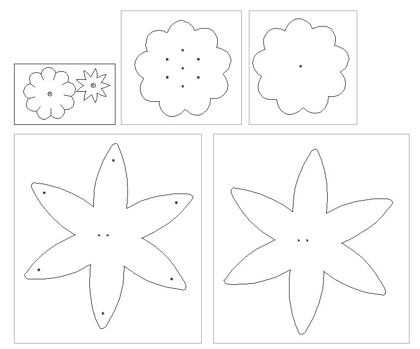
Three functional layers with through-holes (to seperate the positive and negative leads) + 2 decorative layers were designed in illustrator and lasercut.
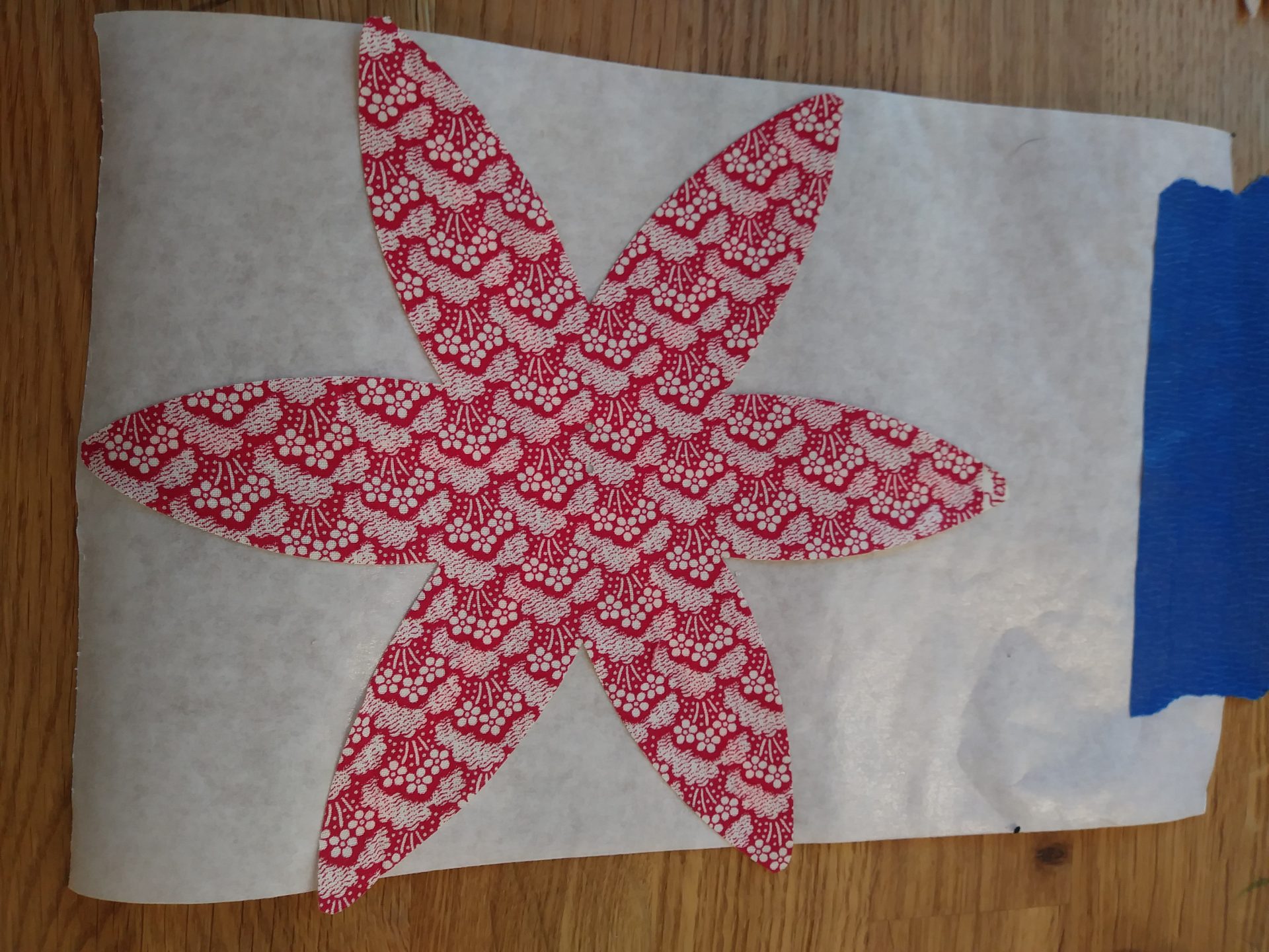
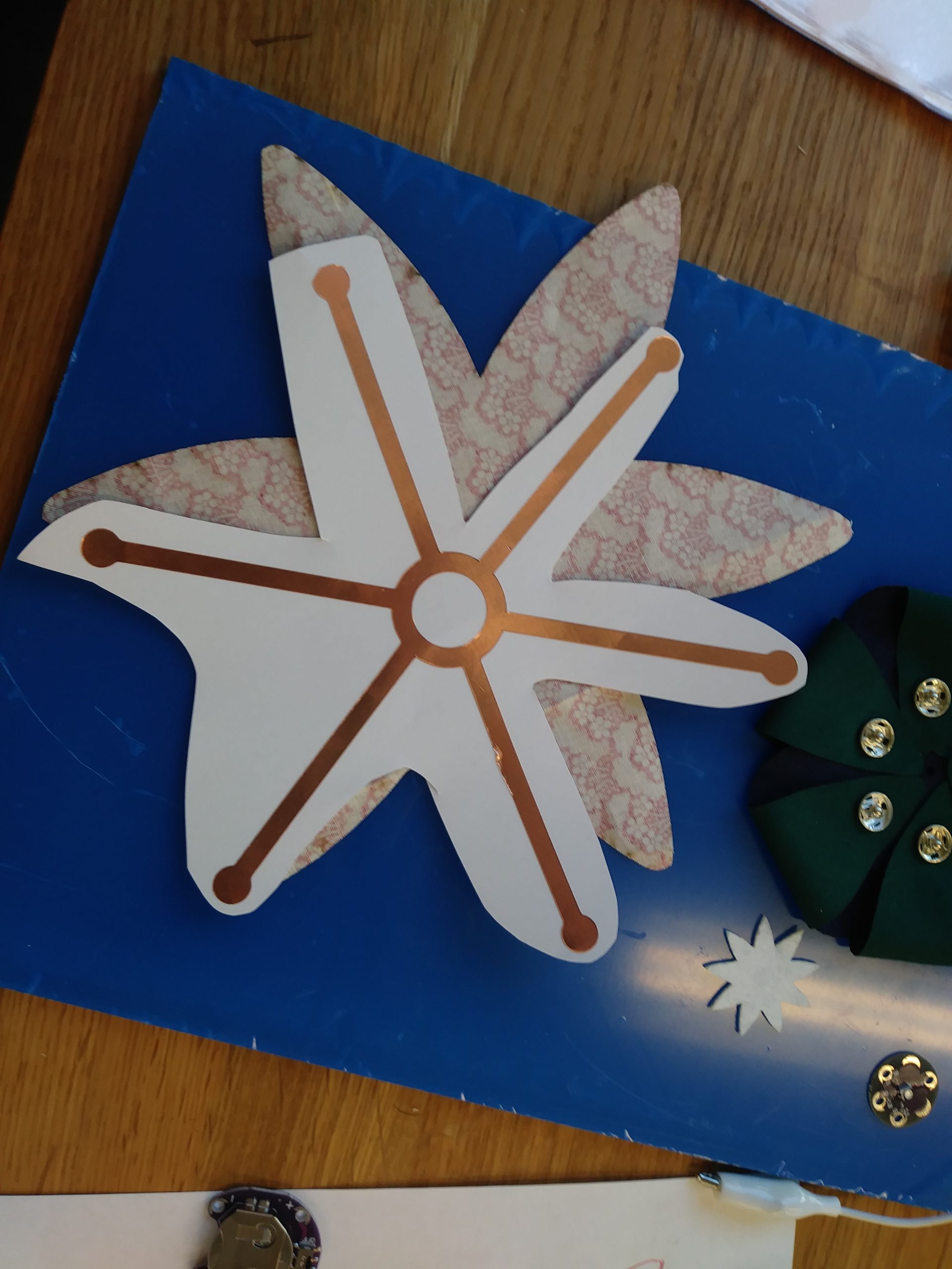
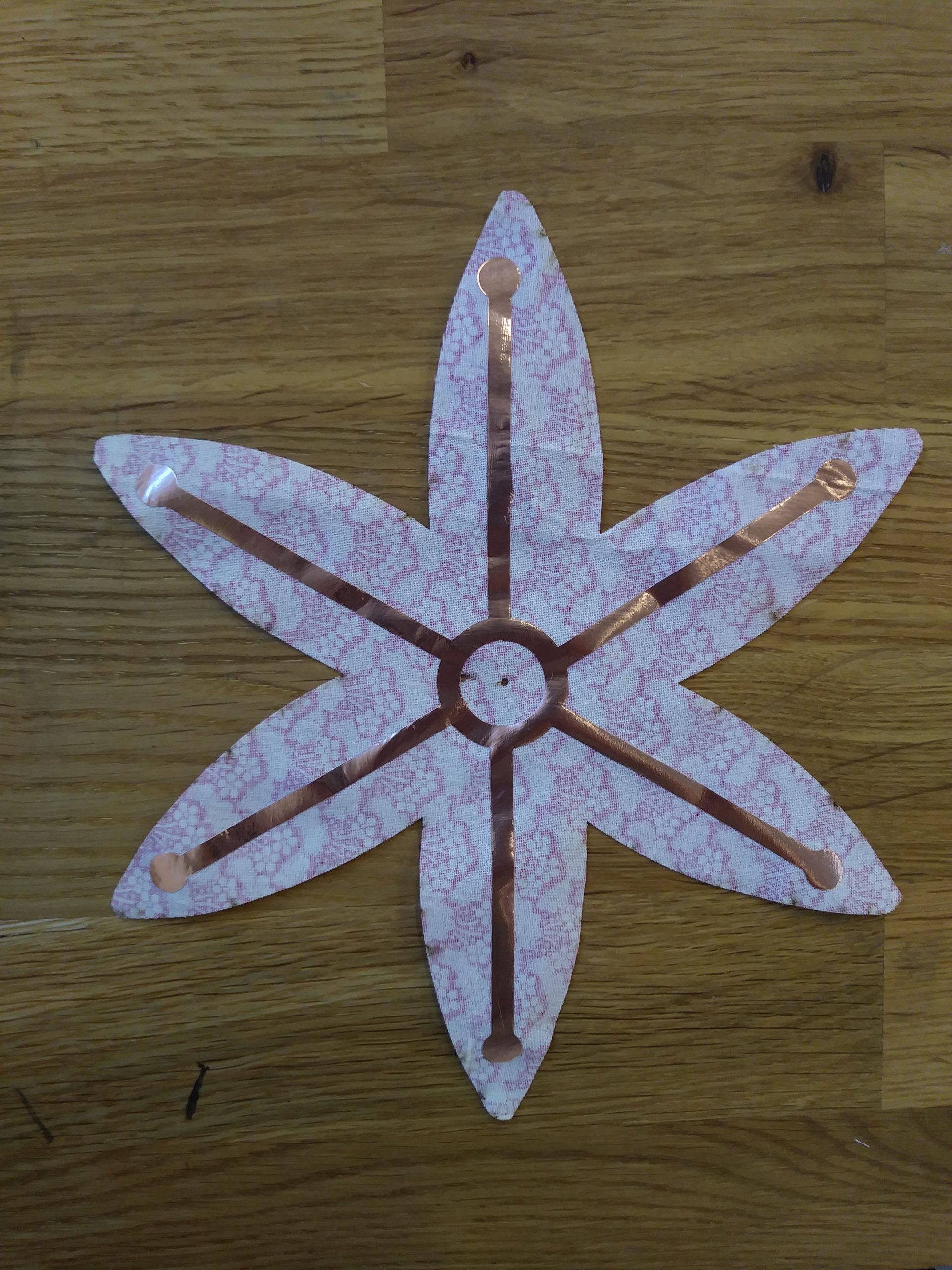
A circuit to supply power to the petals (flower power!) was similarly designed and cut out of a copper sheet using a vinyl cutter. This was then transferred to the back layer of the flower as shown.
Assembly
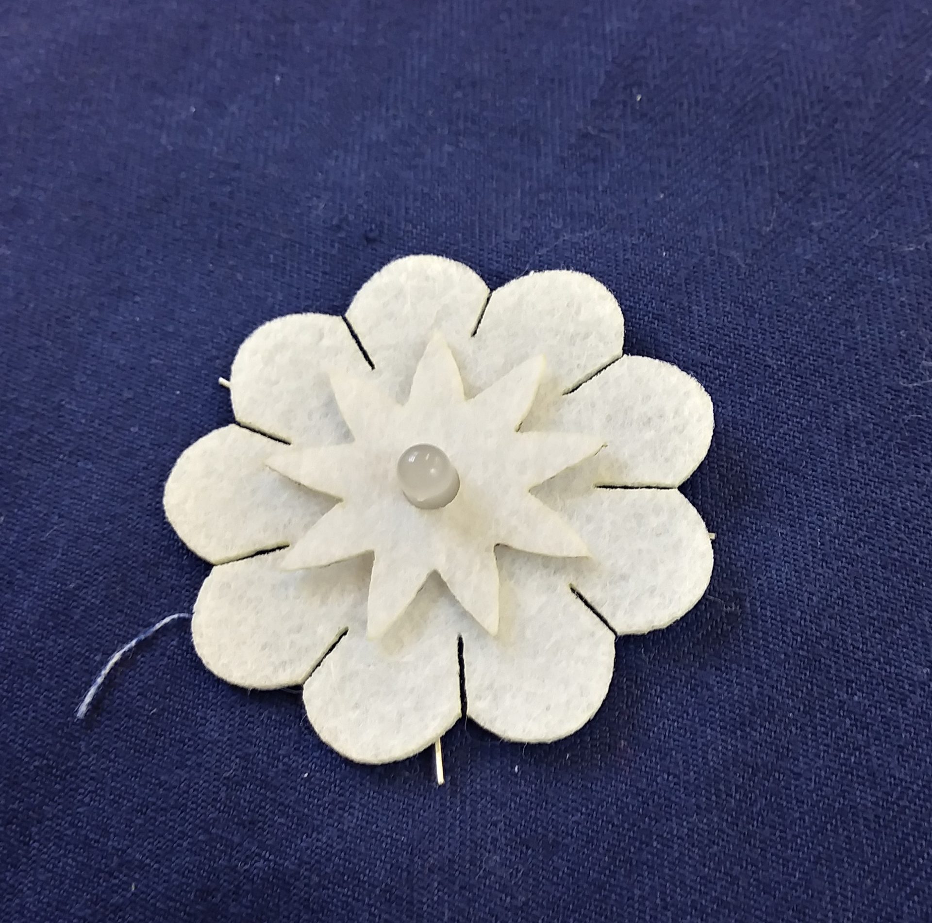
Here are the three functional layers of the flower:
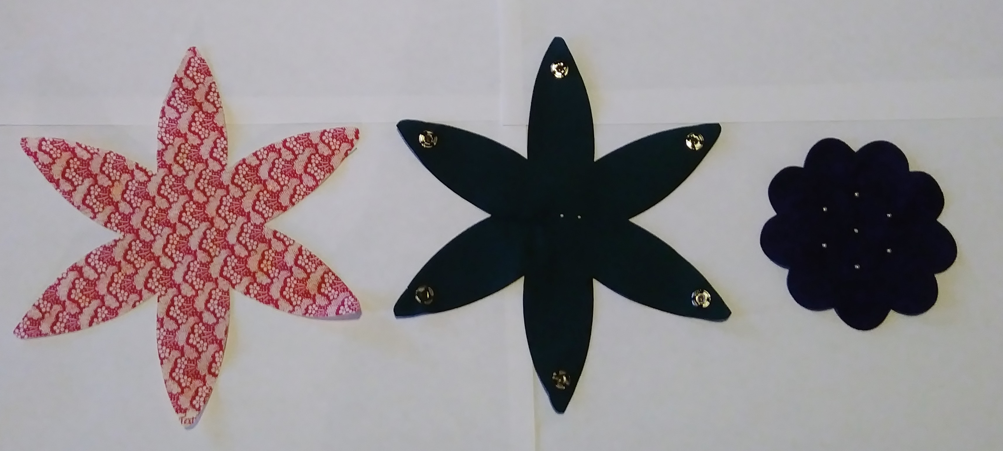
Back : Note the conductive snaps are sewn into the middle layer, in-line with the through-holes, serving as a bridge between the first and second layer.
Front : Note the same sewing process is applied to the front of the third layer.
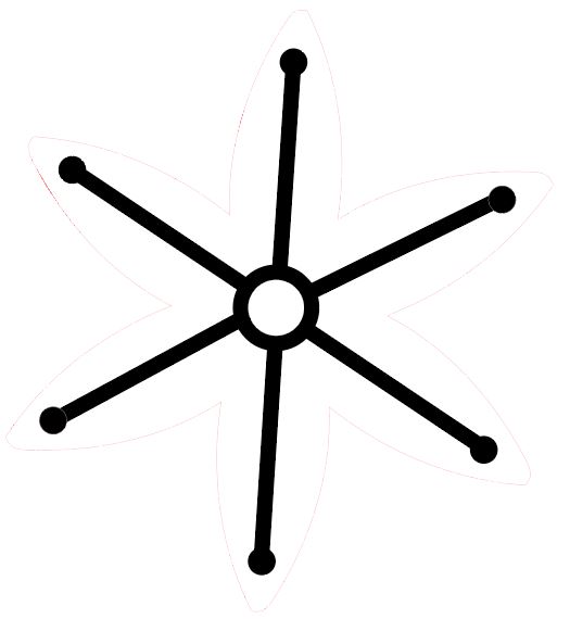
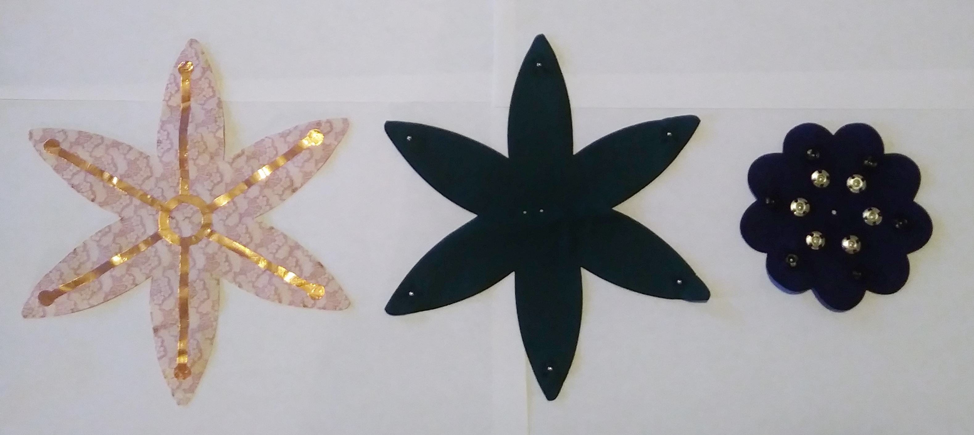
The Copper Circuit is then soldered to the second layer’s snaps, the LED is placed between the the second and third layer, with its positive leads being soldered to the remaining snaps in the following configuration:
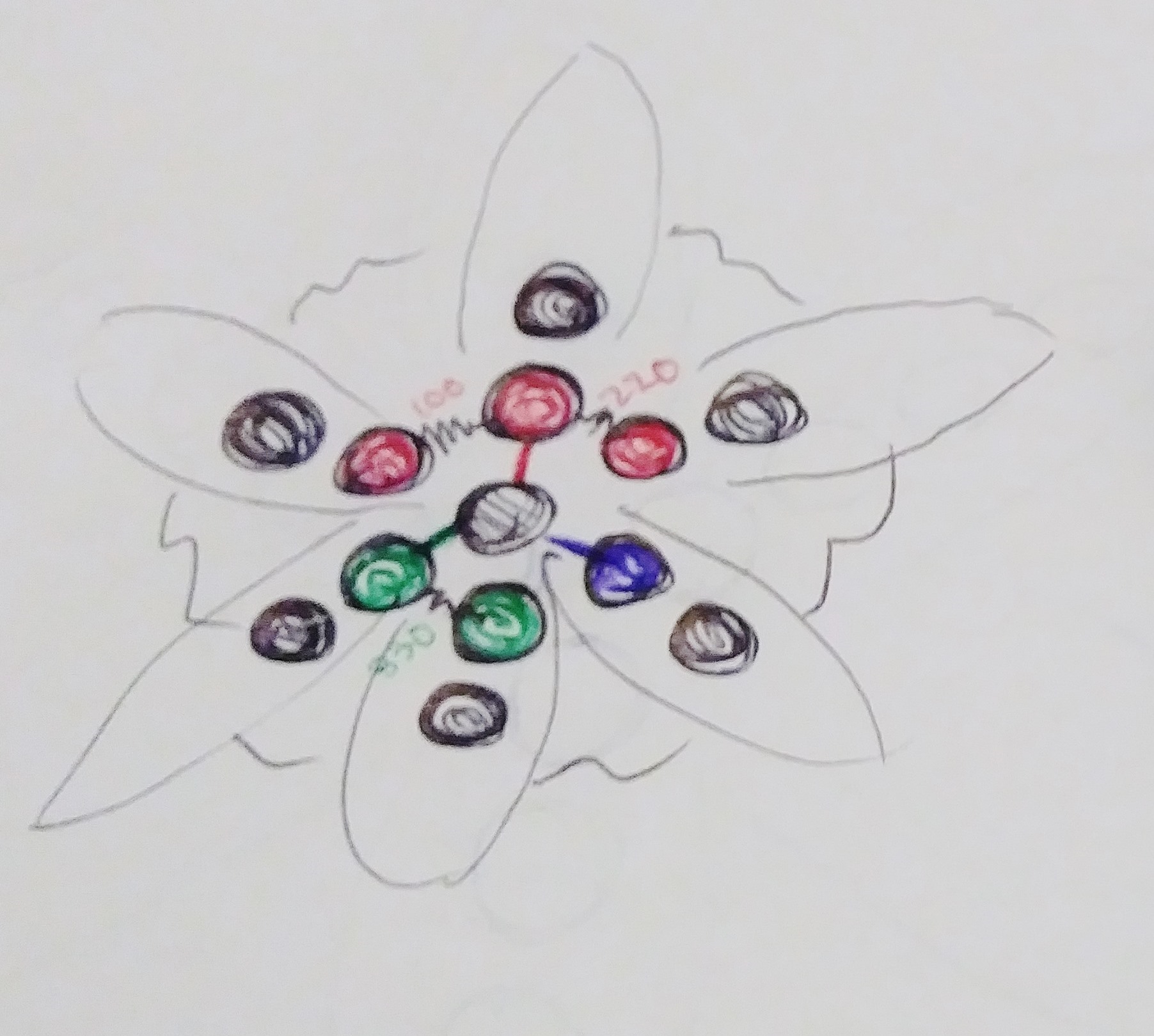
The vertical pin is the ground, which will go through all the layers to the battery. Not shown is the positive lead, which runs through the 1st layer and connects to the copper circuit.
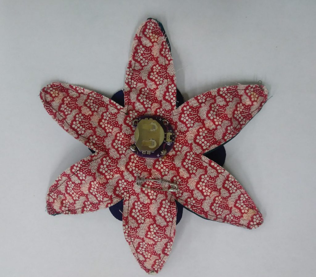
After all electrical connections are properly soldered, the layers are sewn together around their perimeter.
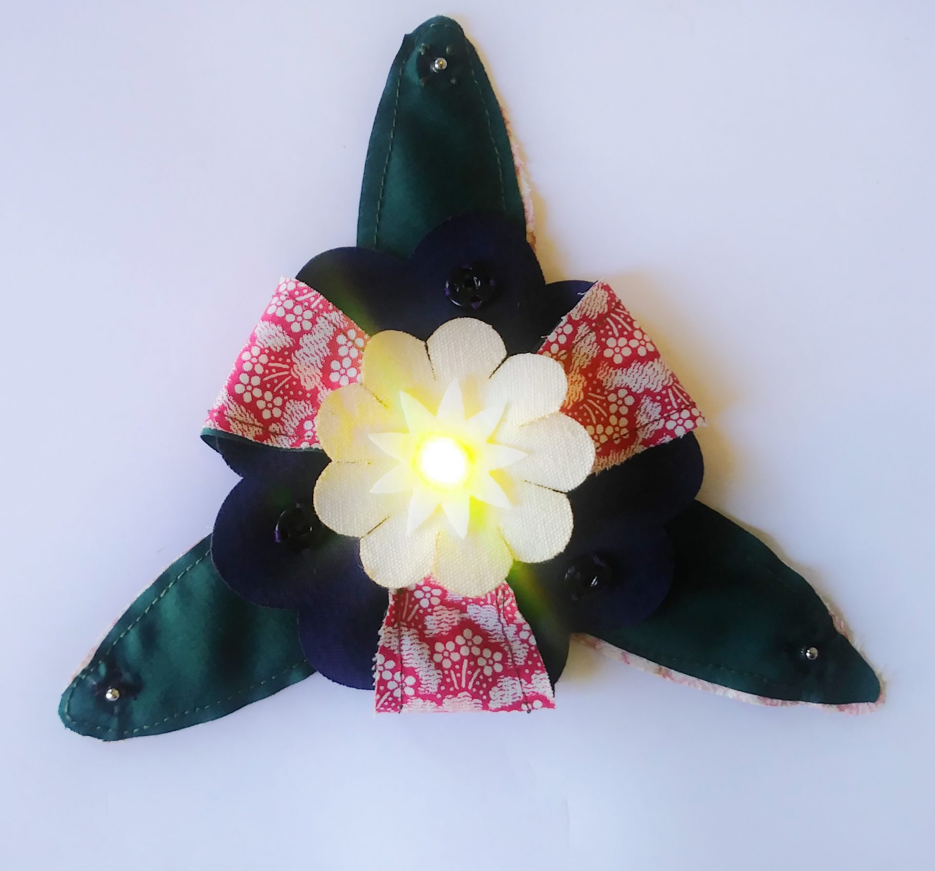
Final Design:
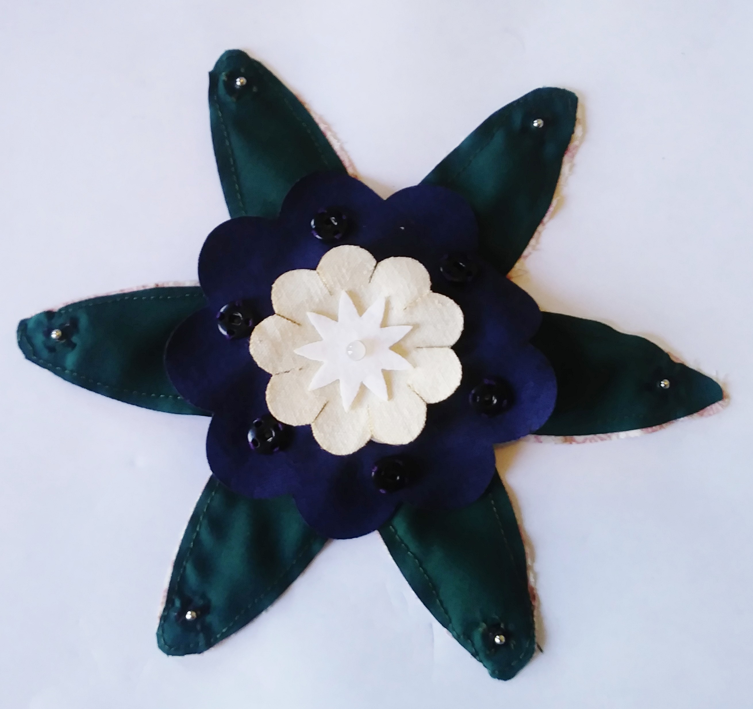
Flower1
Flower2
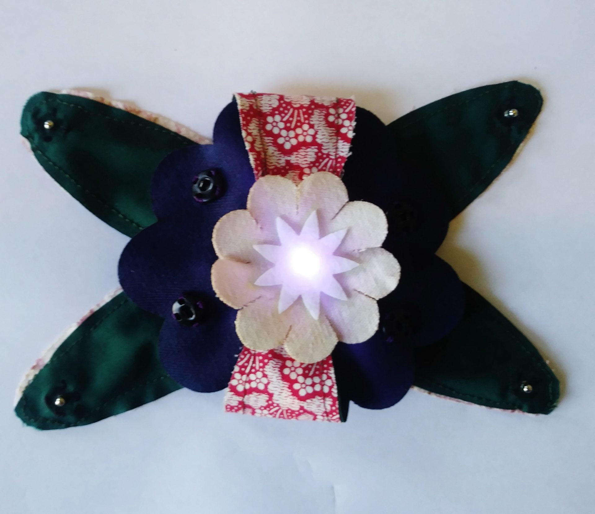
Flower3
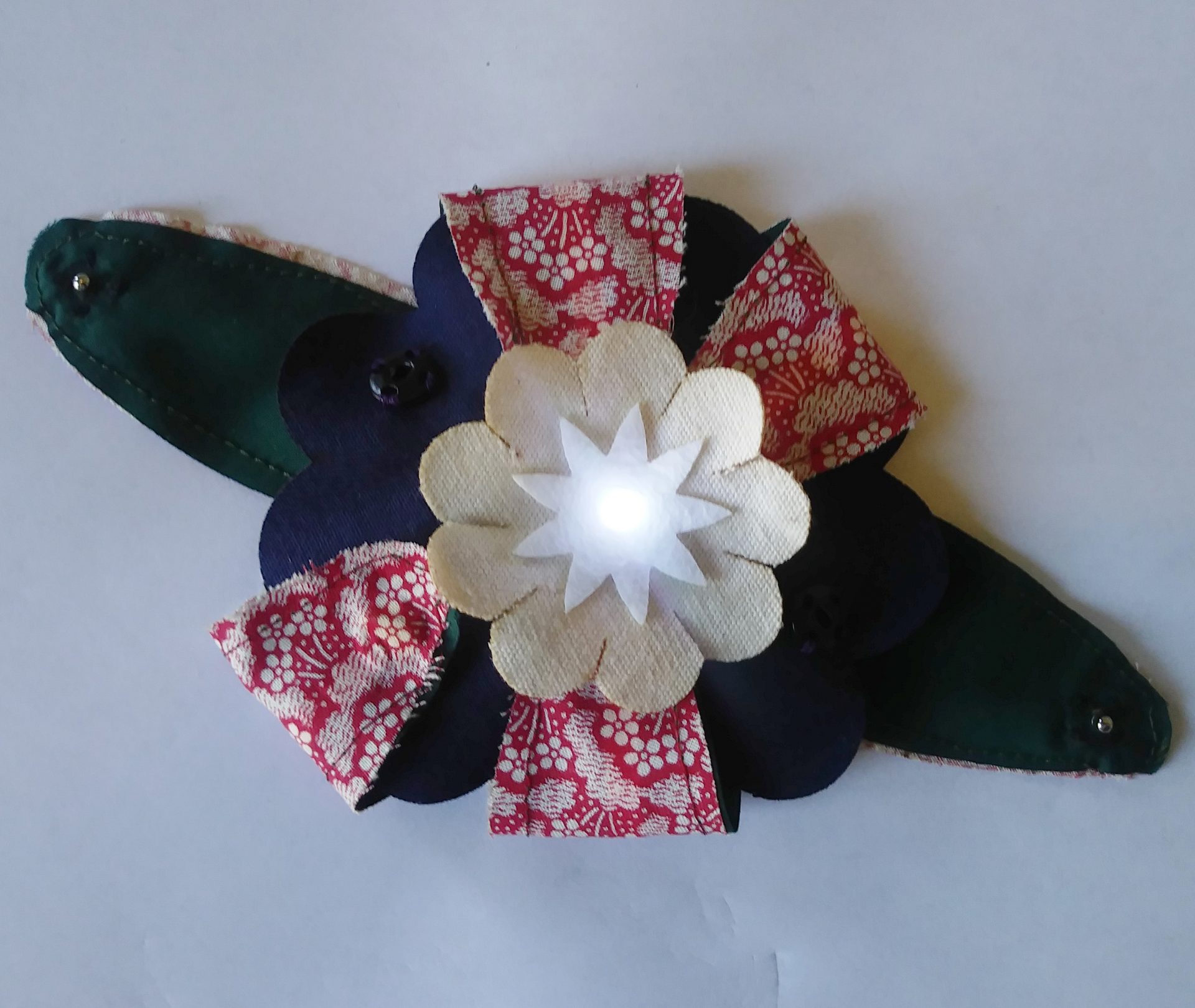
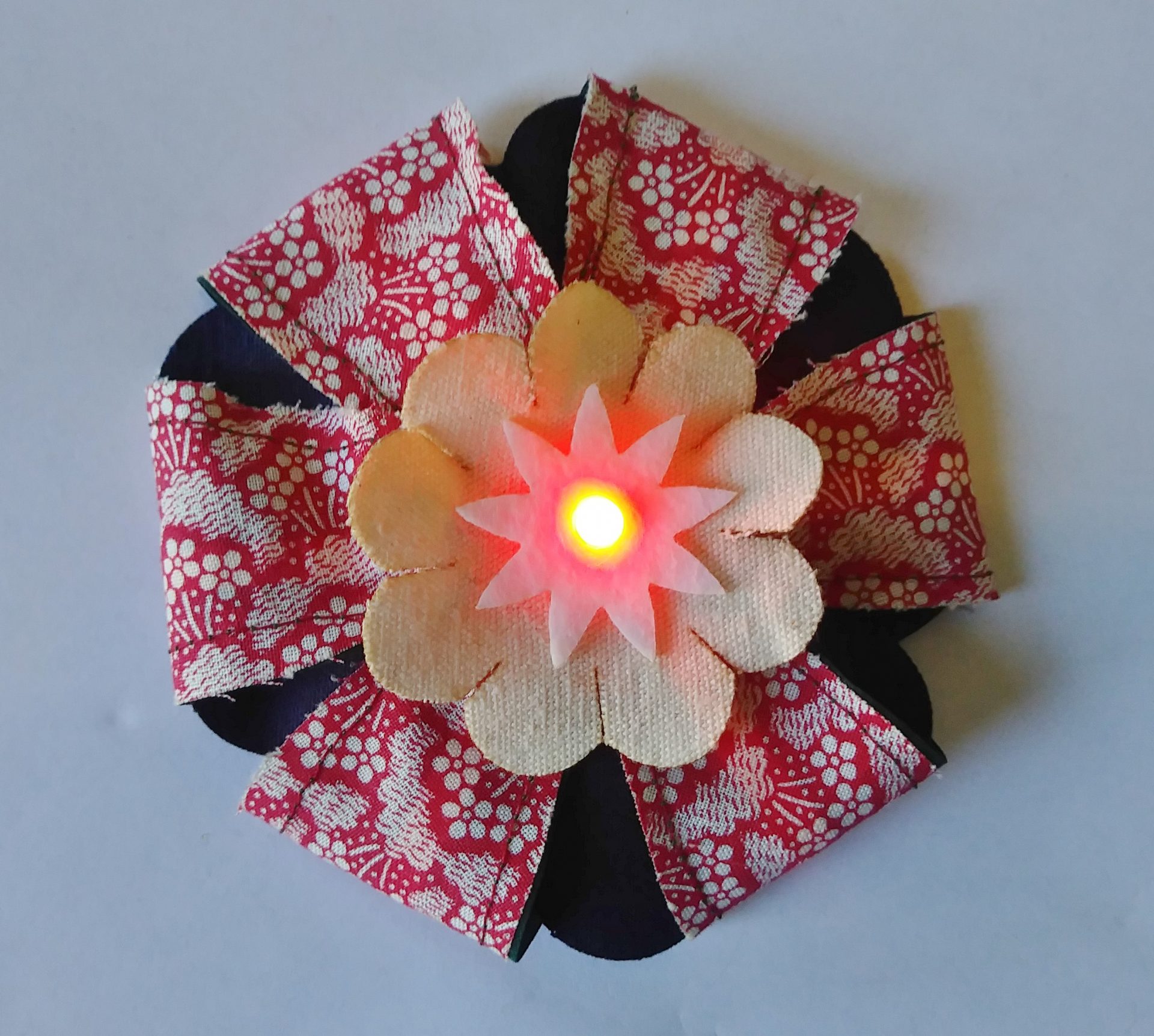
Flower4
Note: For durability, the resistors should be sewn into the circuit using conductive thread. The use of regular solder method was pure lazyness.
Conclusion:
E-textiles is very time consuming for such a limited payoff – maybe worth it for specific applications, but generally restrictive way to build circuits unless you have the right materials.