Layers
TurningLiner_small
shrink_fit_demo_small

IMG_20170602_141452_small
Background
Sponsored by the Portland State University Aerospace Society and with Oregon Space Grant Consortium NASA funding, I and five other PSU Mechanical Engineering students tackled the problem of Liquid Oxygen fuel containment for PSAS’ Generation 4 rocket. PSAS’s ultimate goal is to reach the Von Karman Line, an imaginary boundary 62 miles above sea level, that defines where Earth’s atmosphere ends and space begins.
With each generation rocket, PSAS attempts to improve control, data collection, and range. On the problem of range, rockets often butt up against the reality of the rocket equation – which describes the interplay of mass, force, and velocity. Basically, you need a certain amount of fuel to generate enough force to attain the requisite speed to escape earth’s gravity, but that fuel increases the weight of your rocket, which increases your inertia, which slows you down….
So, if you want your rocket to get to space, you can’t simply make it bigger, you must also improve it’s mass to propellant force ratio.
This can achieved in a few ways:
- reduce the initial weight of your rocket (through lighter-weight materials)
- reduce the weight of your rocket during flight (through multi-stage rockets or jettisoning spent fuel)
- use fuel with a more efficient force to mass ratio
PSAS is pursuing all three options by 1. transitioning from an aluminum to carbon-fiber body design and 2 & 3. switching from solid fuel to liquid propellant (burns off during flight & is more powerful than solid fuel).
Project
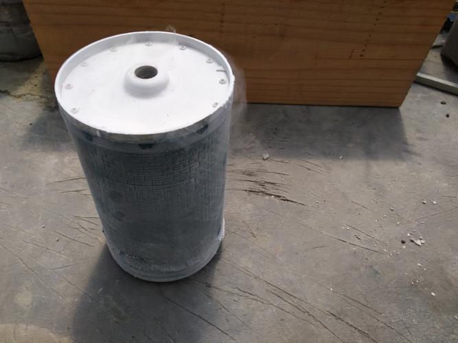
Our goal was to build a proof of concept liquid oxygen tank that could withstand expected flight stress and inevitable internal pressure build-up, while also integrating a lighter-weight carbon-fiber body.
Our biggest challenge was the fact that liquid oxygen likes to react with almost anything, including carbon-fiber composite material and adhesives (NASA & SpaceX have access to non-reactive composites that a university rocket team simply cannot afford/access). Traditional aluminum tanks are popular as they don’t have this reactivity problem, but again add weight.
Solution
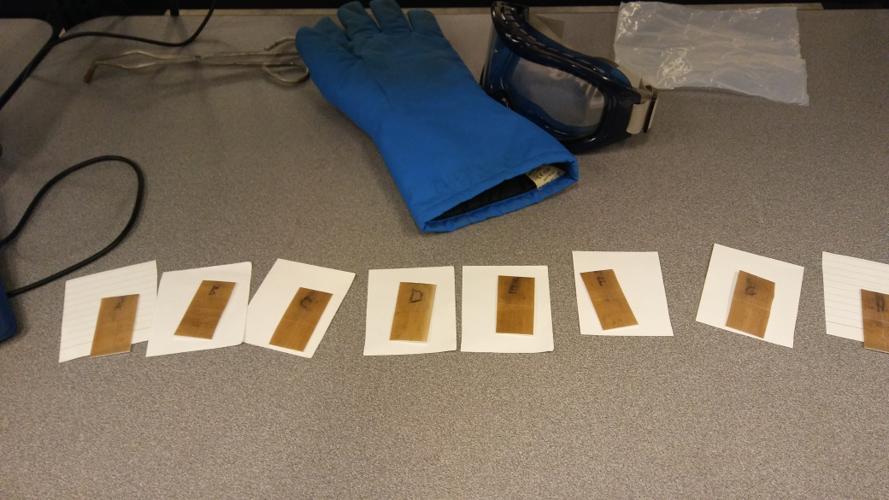
Our solution involved the hand-machining of a custom PTFE inner hull, which provided a non-reactive internal barrier and precisely CNC-machined aluminum endcaps. We then leveraged the natural thermal contraction properties of our materials to create a mechanical seal between liners and endcaps though shrink-fitting. This design isolated the LOX from the carbon-fiber hull and withstood the minimum internal and external pressures by a safety factor of 2.
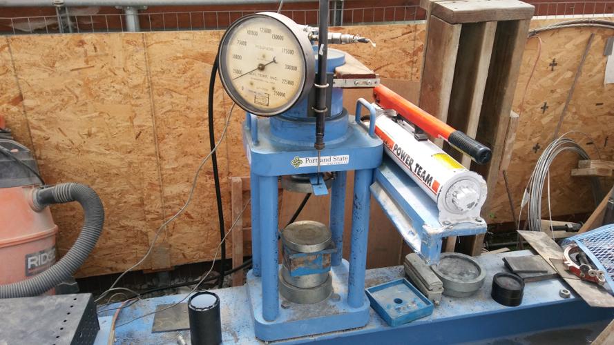
Though the final design was fairly simple and elegant – much material testing and FEA was required to determine final products and dimensions that would be both theoretically functional and feasible to assemble (we only had budget for 2 full prototypes). Happily our second prototype met our benchmarks.
PSAS_Tank_Layup_Process

PTFE Cryo Experiment2_small

PTFE Cryo Experiment1_small
20170528_145611_small

Compression_Tester_small
IMG_20170602_141520_small
IMG_20170602_141452_small
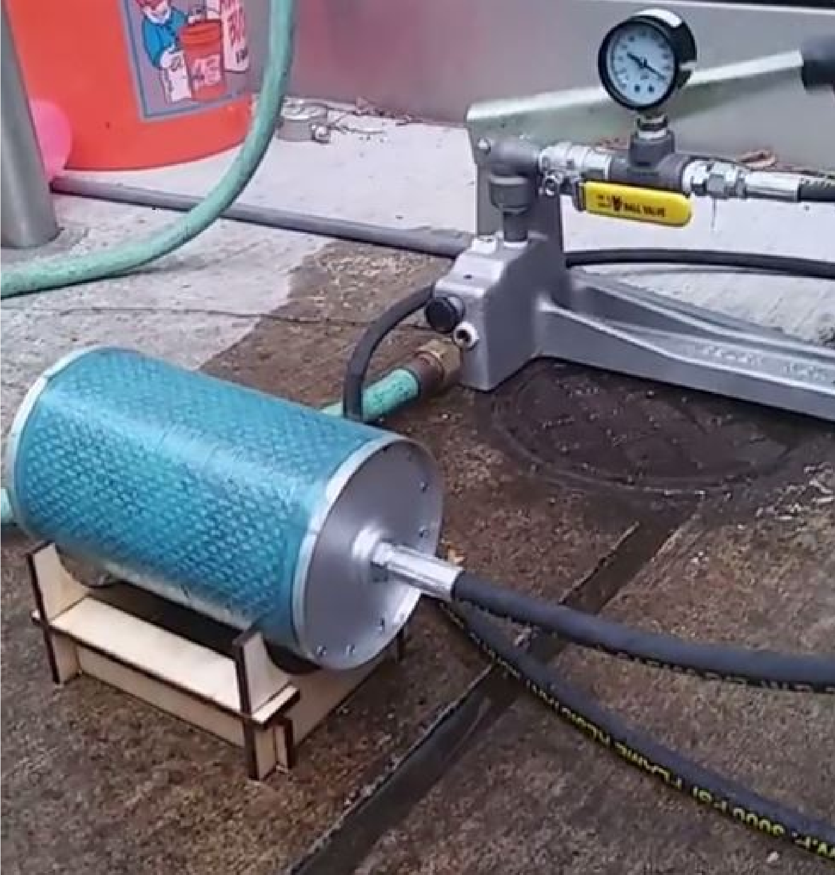
PressureTest
CryoTestGraph

Future
Next steps would be for a future team to scale up this design and test in conjunction with Electric Fuel Injection System (project that was being developed in parallel), or an assessment of whether the weight saved by moving from a machined/welded aluminum to composite adhesive/shrink-fit tank is worth the increased cost and failure modes associated with this design.
I imagine with the rapid innovation and cost reduction occurring in the SLS 3D printing realm, a 3d printed tank might also become a viable option.
Relevant Links:
Design and Manufacture of Liquid Oxygen Propellant Tank for University Rocket | AIAA SPACE Forum